Hello, welcome to Huaxin

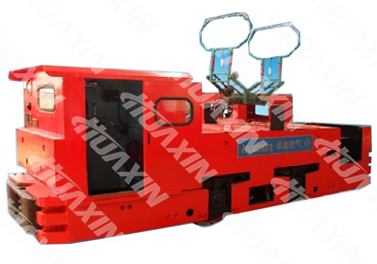
Overhead Line Electric Locomotive
The Overhead Line Mining Electrical Locomotive is manufactured according to the MT/T 1064-200 Specification of the Mining Narrow Tramroad Gauge Trolley Electric Locomotive, and is applicable for the general metal ore and the coal mine which free of methane or coal dust explosion hazard. It can be taken as the main traction equipment for mineral and equipment transport in the underground main roadways or adit. The locomotive is also installed with the wing plates, so as to adapt to demands for transport with the bottom-dump mine cars.

Technical Parameters
Category
Project Name
Technical Data
CJY7/6.7.9GP
CJY10/6.7.9GP
CJY14/6.7.9GP
Traction
Feature
Adhesion Mass (t)
7
10
14
Traction Motor Power * Number (KW×set)
22 × 2
30 × 2
45× 2
Hourly Braking and
Tractive Force (KN)
13.77
18.78
21.3
Maximum Traction Force (KN)
17.15
24.5
34.3
Hourly Speed (km/h)
11
10.5
14.7
Traction Height (mm)
320/435
320/435
320/435
Braking Mode
Mechanical + Electrical
Mechanical + Electrical
Mechanical + Electrical + Air
Appearance
Feature
Gauge (mm)
600/762/900
600/762/900
600/762/900
Axle Base (mm)
1100
1100
1700
Wheel Rolling Circle Diameter (mm)
680
680
760
Minimum Radius of Curvature (m)
7
7
12
Height from the Rail Surface
to the Ceiling (mm)
1600
1600
1600
External Dimensions (mm)
4480 ×1050 ×1600
4480 ×1212 ×1600
4480 ×1350 ×1600
4500 ×1050 ×1600
4500 ×1212 ×1600
4500 ×1350 ×1600
4950 ×1050×1600
4950 ×1212 ×1600
4950 ×1350 ×1600
Category
Project Name
Technical Data
CJY18/6.7.9GPY
CJY20/6.7.9GPY
Traction
Feature
Adhesion Mass (t)
18
20
Traction Motor Power * Number (KW×set)
63 × 2
63× 2
Hourly Braking and
Tractive Force (KN)
37.2
37.2
Maximum Traction Force (KN)
44.1
49
Hourly Speed (km/h)
11
11
Traction Height (mm)
320/435
320/435
Braking Mode
Mechanical + Electrical
Mechanical + Electrical
Appearance
Feature
Gauge (mm)
600/762/900
600/762/900
Axle Base (mm)
1700
1700
Wheel Rolling Circle Diameter (mm)
760
760
Minimum Radius of Curvature (m)
12
12
Height from the Rail Surface
to the Ceiling (mm)
1600
1600
External Dimensions (mm)
5400 ×1040 ×1600
5400 ×1202 ×1600
4480 ×1340 ×1600
5400 ×1040×1600
5400 ×1202 ×1600
5400 ×1340 ×1600
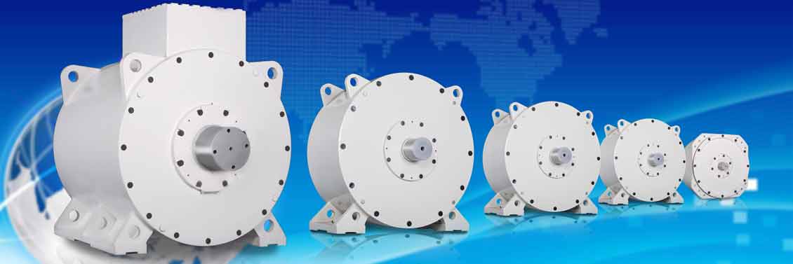
1. Traction Motor: Three-phase Asynchronous Variable Frequency Motor. It has low construction cost, low failure rate, high operation efficiency and strong applicability, and is basically maintenance-free. It can make parameter adjustment in different outlines, so as to meet the design demands of special models.
2. Controller: the frequency conversion speed regulation adopts the microcomputer control, and the digital signal processor (DSP) is the core, which combines the frequency control, vector control and slippage rate perfectly. It is a stepless speed regulation and no mechanical maintenance is needed.
3. Performance:
1) Start, speed regulation, coasting and brake of the locomotive are controlled by changing the operating frequency through microcomputer control.
2) If the speed is adjusted downward from the fundamental frequency, it is a constant torque speed regulation; if the speed is adjusted upward from the fundamental frequency, it is a constant power speed regulation.
3) The speed regulation scope is large, the rotating speed stability is good, and the frequency can be adjusted continuously, which is stepless speed regulation and it is good for the adhesion of locomotives. The slippage rate is small and the efficiency is high during operation.
4) It can achieve intelligent control and stable operation, which extends the service life of the mechanical components.
4. Energy Consumption: variable frequency speed control is constant torque output control at or below rated frequency, and the energy saving effects are obvious plus regenerative braking.
The locomotive has a two-axle steel frame, the structure is compact, operation is stable and manipulation is centralized. It consists of a frame, a cab, a buffer, a braking device, a sanding device, a travel device, a spring suspension system, an electrical equipment system and other main parts.
Mechanical Part
The mechanical part mainly consists of a carbody, carbody accessories, a travel device, a braking device, a sanding device, a cab, a damping device and a buffer. The mechanical energy generated by the traction motor is transferred to the travel device, and provides the traction power to the locomotive, i.e., tractive force of the wheel flange.
1. Carbody Composition
The carbody is a frame structure that welds the left and right side, front and rear end plates and intermediate diaphragm together. The carbody is connected with the travel device by being supported on its bearing box through four groups of vibration dampers. The buffers are installed at the front and rear end plates of the carbody, so as to mitigate impact and couple the mine cars.
2. Travel Device
The travel device consists of a gearbox, wheelsets, an axle box and other parts. There are two groups for each locomotive.
The housing of the gearbox is casted with ZG230-450 steel and consists of upper and lower halves. The upper casing and the traction motor shell are fitted with the rabbet, and connected with bolts. It is semi-suspended on the frame with the damping spring.
The wheelset consists of wheels, wheel axles, a bearing box, etc. The wheel consists of a wheel hub and a wheel rim through hot press-fitting, the wheels and the wheel axles are subject to cold press-fitting, the bearing box is installed at both ends of the wheel axle, the box is cast with ZG270-500 steel, which withstands the weight of all equipment of the locomotive. Locomotive traction in the horizontal direction is transferred to the carbody through the rail of the bearing box.
3. Braking Device
Mechanical brake and electric brake are adopted for the locomotive. The braking resistor arranged on the electric locomotive is mainly used for speed limit of the locomotive uphill or downhill. In order to completely stop the locomotive the mechanical brake is also required, so that the brake shoe is close to or separated from the wheel flange to achieve system brake or release.
The mechanical braking device is used on the locomotive or train for parking on the rampway. The drivers rotate the handwheel in the clockwise direction, so as to drive the crossbeam, pull rods and connecting rods through the screw rods and nuts, and drive the brake shoe to brake or release two groups of wheels simultaneously. After the brake shoe is worn, the brake shoe clearance regulator can be adjusted, so that the clearance of 2-3mm is maintained between the brake shoe and the wheel flange. Adjust the spring leaf with the adjusting screw, so that the gap between the working surface of the brake shoe and the wheel tread is maintained uniform, so as to guarantee the braking effect.
4. Sanding Device
Manual sanding principle is utilized for the device, and there are four sand boxes near four wheels of the locomotive. Sanding can be conducted to the rail when brake is applied to the locomotive, so as to increase adhesion coefficient between the wheel rim and rail surface. When the locomotive travels forward, front sanding works; when the locomotive travels backward, rear sanding works.
5 Cab
The cab is installed at the front of the locomotive. The cab consists of a roof, a front board, left and right side plates and a back plate, which completes a closed structure. It can prevent rainwater, falling rock, etc, so as to protect driver’s safety. The observation window is opened at the front end, and the lighting signal lamp is installed. The controller, brake handwheel, etc, are arranged in the cab.
6. Damping Mechanism
The plate spring damping mechanism of the CJY7/6, 7, 9GPY, CJY10/6, 7, 9GP Overhead Line Mining Electrical Locomotives consists of four groups of plate springs, plate spring connecting rods and equalizing beams. It plays the role of damping. Each group of plate springs is located in the dimple of the axle box and is connected with the travel device through the lug boss at the bottom spring hoop. Both ends at the upper of the front two groups of plate springs are connected with the carbody through the plate spring connecting rod and the equalizing beam, and both ends at the upper part of the rear two groups of plate spring are connected with the carbody through the plate spring connecting rod. The two front groups of plate springs adjust the axle weight at both ends through the equalizing beam, which facilitates counterweight balancing of the whole vehicle.
The CJY14/6, 7, 9GP, CJY18/6, 7, 9GPY, CJY20/6, 7, 9GPY, CJL18/6, 7, 9GP Overhead Line Mining Electrical Locomotives adopt a rubber damper. The vibration damper shall be suspended on the left and right side plates of the frame, and be supported on the wheelset bearing box, so as to play the role of damping.
7. Buffer
The buffer consists of a buffer frame, a buffer seat, an upper cover plate, a contact, springs and connecting pins. The buffers are installed on the front and rear end plates of the frame, which play the role in coupling mine car and buffering, and can mitigate impact between the locomotive and the mine cars.
1. The elevation shall not exceed 2,000m.
2. The ambient temperature shall be between -25℃ and 40℃(-13℉ and 104℉).
3. The monthly average maximum relative humidity of the wettest month shall be less than 90%, the average minimum temperature of the month shall not be higher than 25℃/77℉.
4. No gas or dust in the air enabling to cause corrosion or damage insulation.
Contact information
-
About Huaxin
-
Follow Us


-
Share Us
©1996-2023 晋ICP备07500050号 Huaxin Copyright
©1996-2023 晋ICP备07500050号 Huaxin Copyright


